

How To Get Vive Lens Repaired
Introduction
Utilize this guide to remove and replace the lens and OLED frames in an HTC Vive.
You'll need a narrow, long-shaft driver to attain some of the screws in this guide.
-
-
Identify a finger on the top border of the compartment cover assembly and slide the assembly toward the front of the Vive until it comes loose from the headset.
-
Lift the encompass away from the headset and slide it up the cables until information technology'due south out of the mode.
-
-
-
Lift the HDMI cablevision directly up to unplug information technology from the headset.
-
-
-
Repeat the lifting and unplugging process with the remaining USB, ability, and audio cables.
-
-
-
Use a T5 Torx driver to remove the two 12 mm-long screws securing the head strap mounts on either side of the headset.
-
-
-
Remove both head strap mounts.
-
-
-
Slide the facerest straight away from the headset to remove it.
-
-
-
Use tweezers to remove the small stickers over the four screws securing the outer shell.
-
Apply a T5 Torx driver to remove the four iii.4 mm-long screws securing the outer vanquish.
-
-
-
Grasp the top edge of the right half of the outer shell, behind the component embrace and near the seam in the center. Pull it to the right and upwards, away from the headset to release the clip securing that role of the crush.
-
-
-
Grasp the right one-half the outer shell and pull it to the correct and toward the front of the headset in a twisting movement until y'all experience the clips on the front end of the cover release.
-
-
-
Slide the correct side of the outer crush to the correct and off of the headset.
-
-
-
Repeat the last iii steps for the left side of the outer shell and remove information technology.
-
-
-
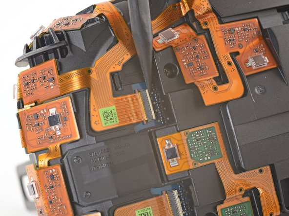
Apply tweezers to remove the clear tape over all four of the sensor array cable connectors.
-
-
-
Utilise the pointed end of a spudger to flip up the minor locking flap on ane of the sensor array ZIF connectors.
-
Slide the cable straight out of its socket on the motherboard.
-
-
-
Repeat the previous footstep for the remaining three sensor assortment cables to disconnect the remaining cables.
-
-
-
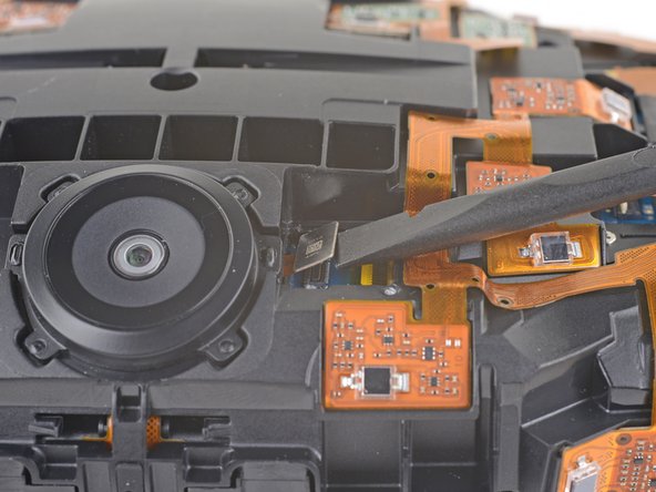
Apply tweezers or a spudger to pry upwardly the camera cable cover and remove it.
-
-
-
Use the flat end of a spudger to pry the camera cable connector straight up from its socket on the motherboard.
-
-
-
Use a PH000 driver to remove the v three.ix mm screws securing the sensor array.
-
-
-
Apply a PH000 commuter to remove the iv three.9 mm screws securing the sensor array.
-
-
-
Use a PH000 driver to remove the four three.9 mm screws securing the sensor assortment.
-
-
-
Lift the sensor array away from the headset to remove it.
-
-
-
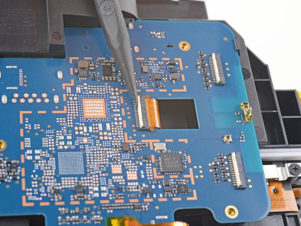
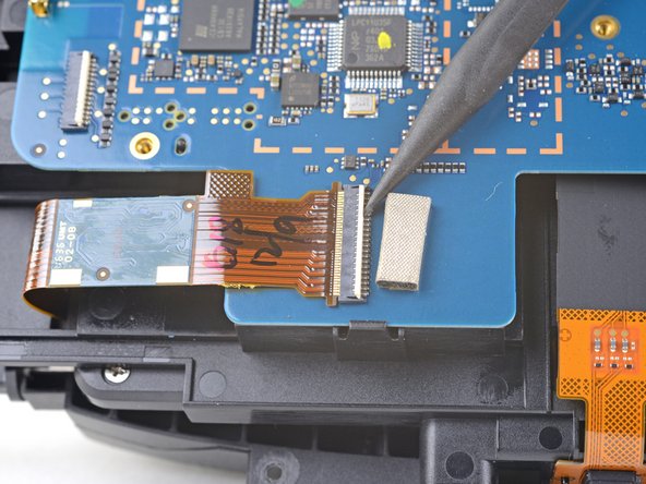
Remove the tape covering the interconnect cable socket.
-
Use the point of a spudger to flip up the minor locking flap on the cablevision socket.
-
Slide the interconnect cable direct out of its socket on the motherboard.
-
-
-
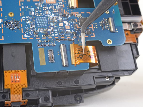
Remove the record covering the left OLED cable socket.
-
Use the point of a spudger to flip up the small locking flap on the cablevision socket.
-
Slide the left OLED cable straight out of its socket on the motherboard.
-
-
-
Remove the record covering the correct OLED cable socket.
-
Employ the betoken of a spudger to flip up the small-scale locking flap on the cable socket.
-
Slide the right OLED cable straight out of its socket on the motherboard.
-
-
-
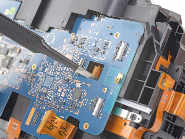
Employ a pair tweezers to slightly twist the interconnect cable and printing it downwardly until the tabs on either side of the cable clear the hole in the motherboard.
-
-
-
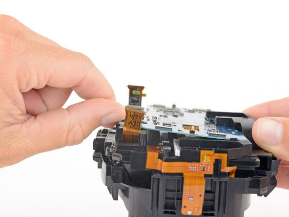
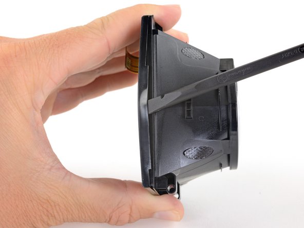
Press the non-port-end of the motherboard toward the elevation of headset while hinging it abroad from the midframe to free it from the clips securing that end.
-
Slide the motherboard toward the lesser of the headset, over the clips, to remove it.
-
-
-
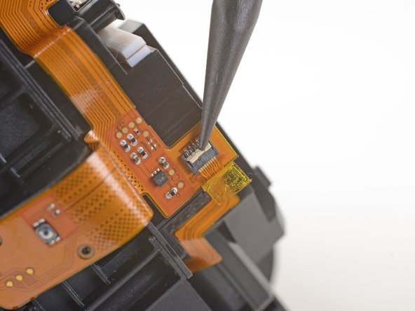
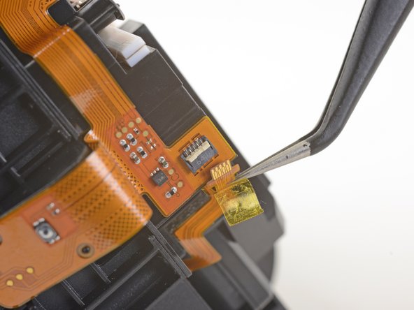
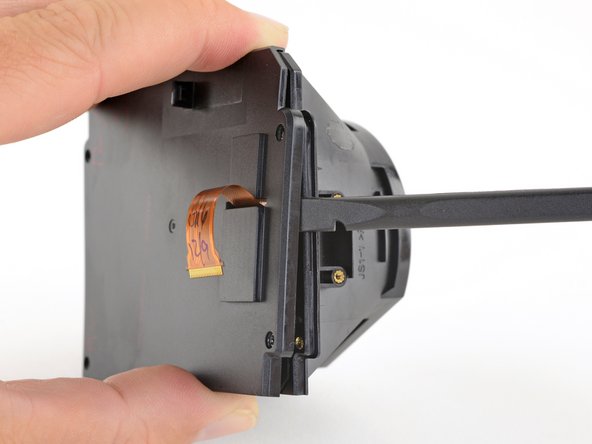
Apply a pair of tweezers to peel back the plastic covering the eyepiece midframe cablevision socket.
-
Apply the pointed end of a spudger to flip up the plastic locking flap on the socket.
-
Slide the cablevision directly out of its socket to remove it.
-
-
-
Gently pare the eyepiece midframe cable off of the facerest midframe.
-
-
-
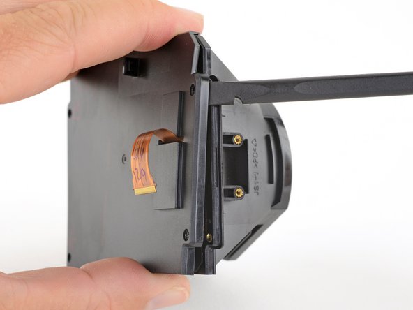
Use a PH000 driver to remove the 4 3.nine mm screws securing the facerest midframe.
-
-
-
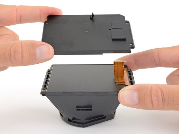
Elevator the facerest midframe off of the eyepiece midframe.
-
-
-
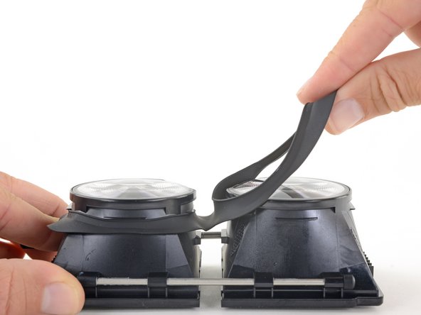
Hinge the OLED and lens frames down and away from the focus knob end of the eyepiece midframe.
-
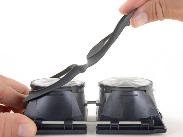
Once you lot've rotated the OLED and lens frame nigh 90 degrees, push button them direct downward, parallel to the face of the eyepiece midframe, to separate them from the midframe.
-
-
-
Gently lift the eyepiece gasket off of the lens and OLED frames to remove information technology.
-
-
-
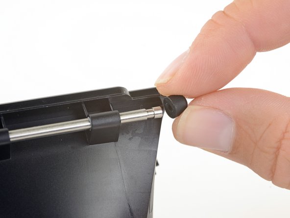
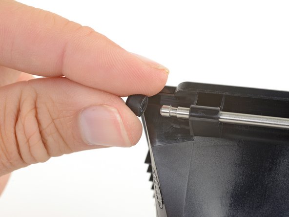
Pull the safety bumpers off of either terminate of the support rod.
-
-
-
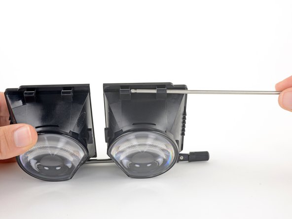
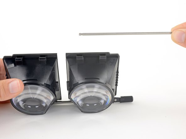
Slide the back up rod out of its brackets on the lens and OLED frames.
-
-
-
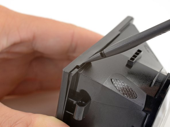
Use a PH000 driver to remove the eight three.1 mm screws securing the focus rod brackets.
-
-
-
Remove the focus rod and its brackets.
-
-
-
Use a PH000 driver to remove the 8 2.4 mm screws securing the OLED covers.
-
-
-
Utilize the apartment terminate of a spudger push button upwards ane edge of the OLED cover and start unclipping that border.
-
-
-
Slide the spudger under the clip along that edge to gratuitous the rest of the edge.
-
-
-
Slide the spudger around the remaining edges of the OLED cover to unclip those edges.
-
-
-
Remove the OLED cover.
-
Repeat the final 3 steps to remove the other OLED cover.
-
-
-
Very advisedly lift the OLED display by its edges out of its frame.
-
Repeat this process for the other OLED brandish.
-
-
-
Use an iOpener to the lens to soften the adhesive securing information technology to the frame.
-
-
-
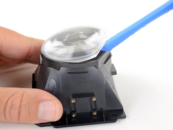
Use an opening tool to pry up the flat edge of the lens.
-
If it's difficult to pry upwardly, employ the iOpener for another 30 seconds to further soften the agglutinative.
-
-
-
Remove the lens.
-
Echo the concluding two steps to remove the other lens.
-
Only the lens and OLED frames remain.
-


Conclusion
Compare your new replacement part to the original office—you may demand to transfer remaining components or remove agglutinative backings from the new part earlier installing.
To reassemble your device, follow the above steps in reverse order.
Take your e-waste to an R2 or e-Stewards certified recycler.
Repair didn't become as planned? Bank check out our Answers community for troubleshooting assist.
Embed this guide
Choose a size and re-create the lawmaking below to embed this guide equally a pocket-sized widget on your site / forum.
Preview

How To Get Vive Lens Repaired,
Source: https://www.ifixit.com/Guide/HTC+Vive+Lens+and+OLED+Frames+Replacement/98123
Posted by: kernlabon1943.blogspot.com
0 Response to "How To Get Vive Lens Repaired"
Post a Comment